LH Rear Inner Wing: B-post Area Repair

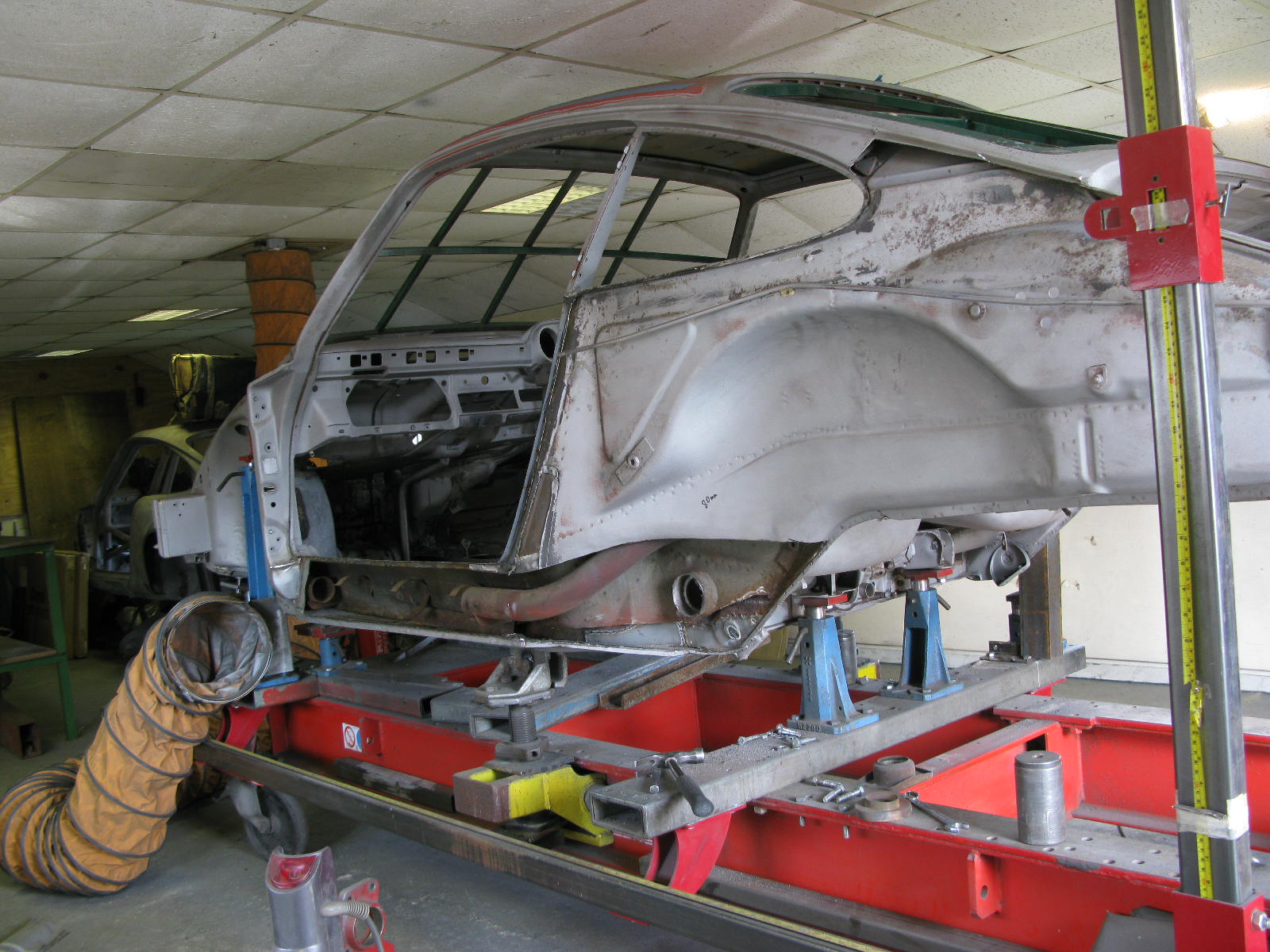
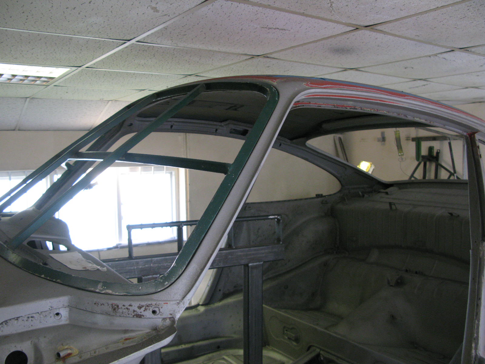
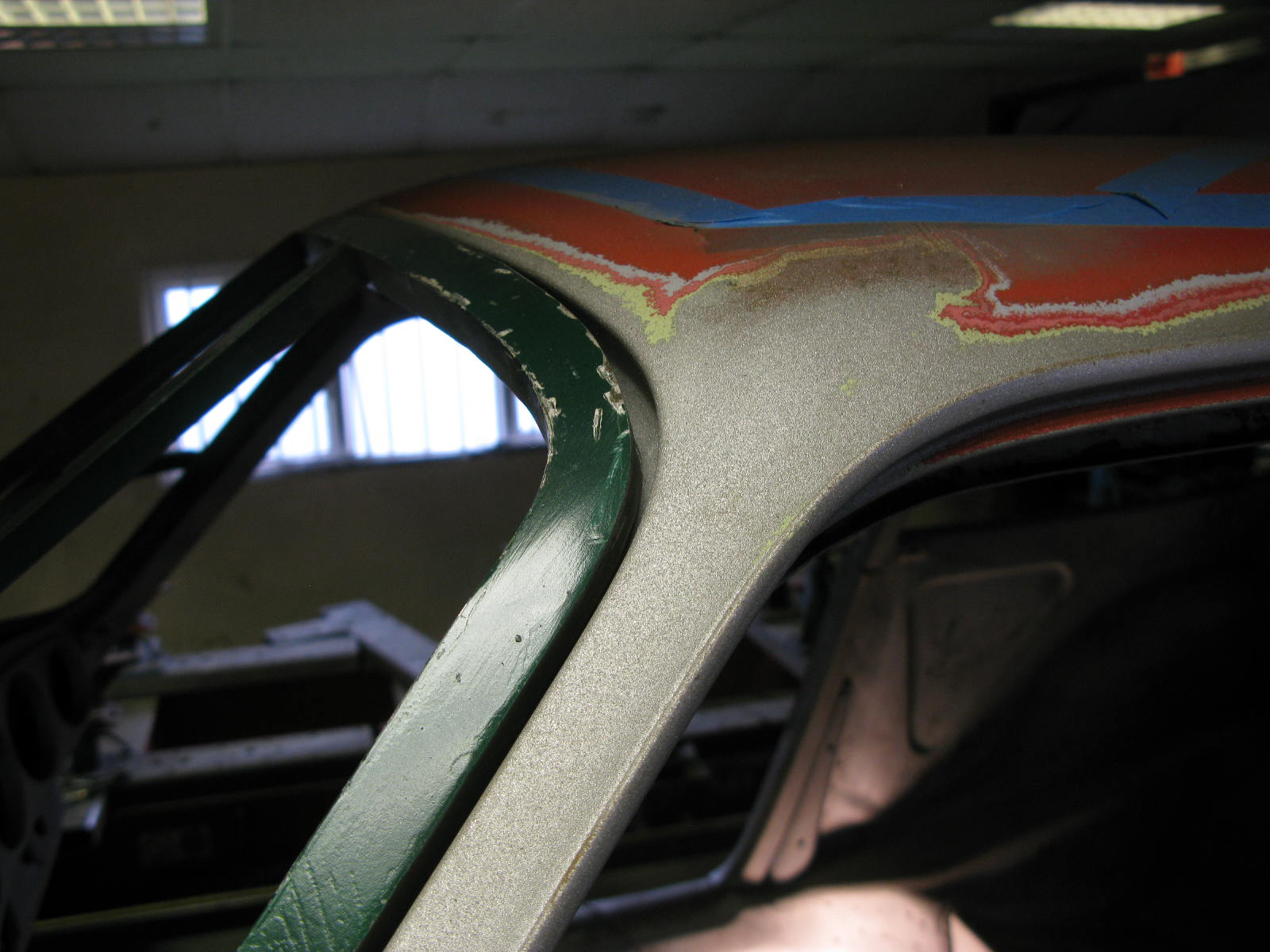
Another area where previous action had taken its toll. As I mentioned the car had been widebody-fied then partially reverted, so had already had 3 sets of rear wings including the original factory ones. I think ours will be the fourth set.

Barry says:
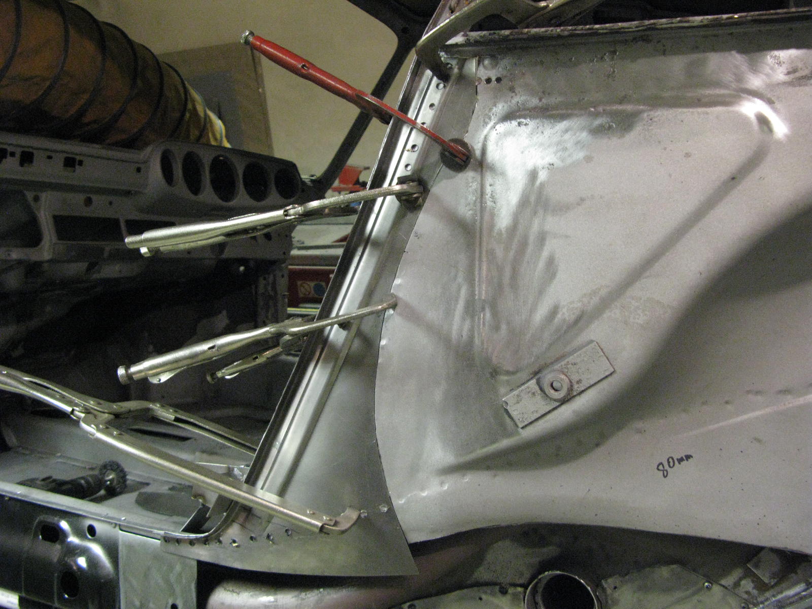
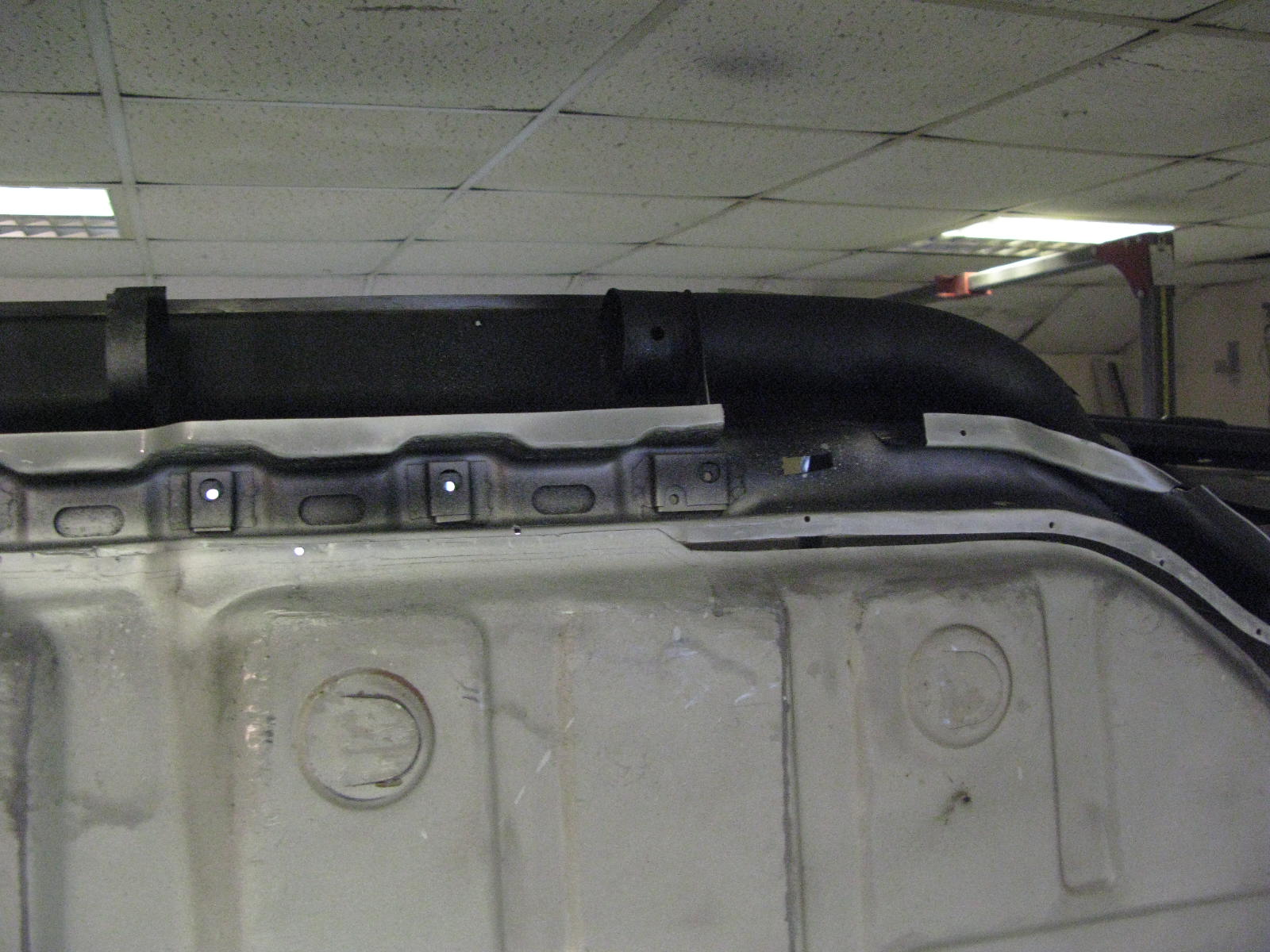
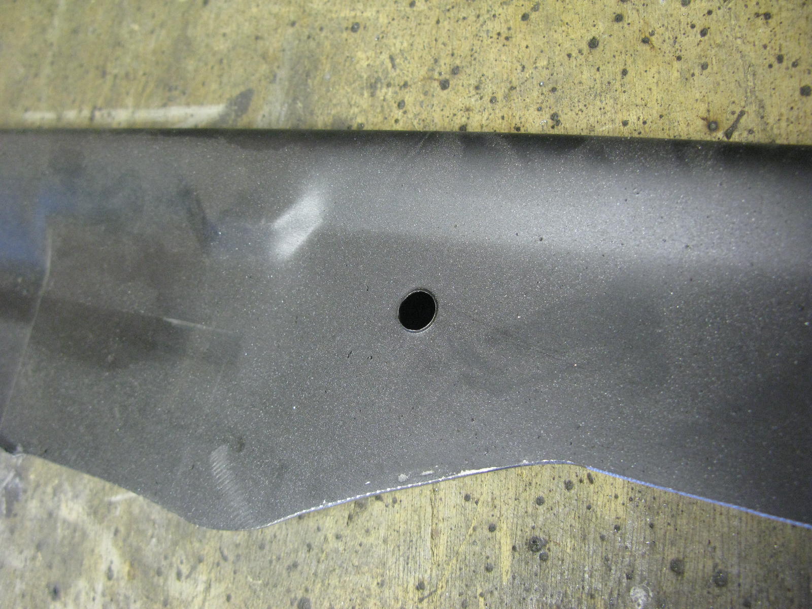
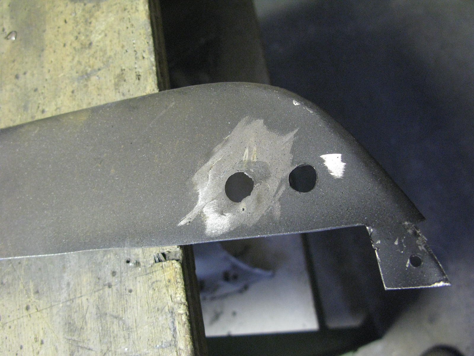
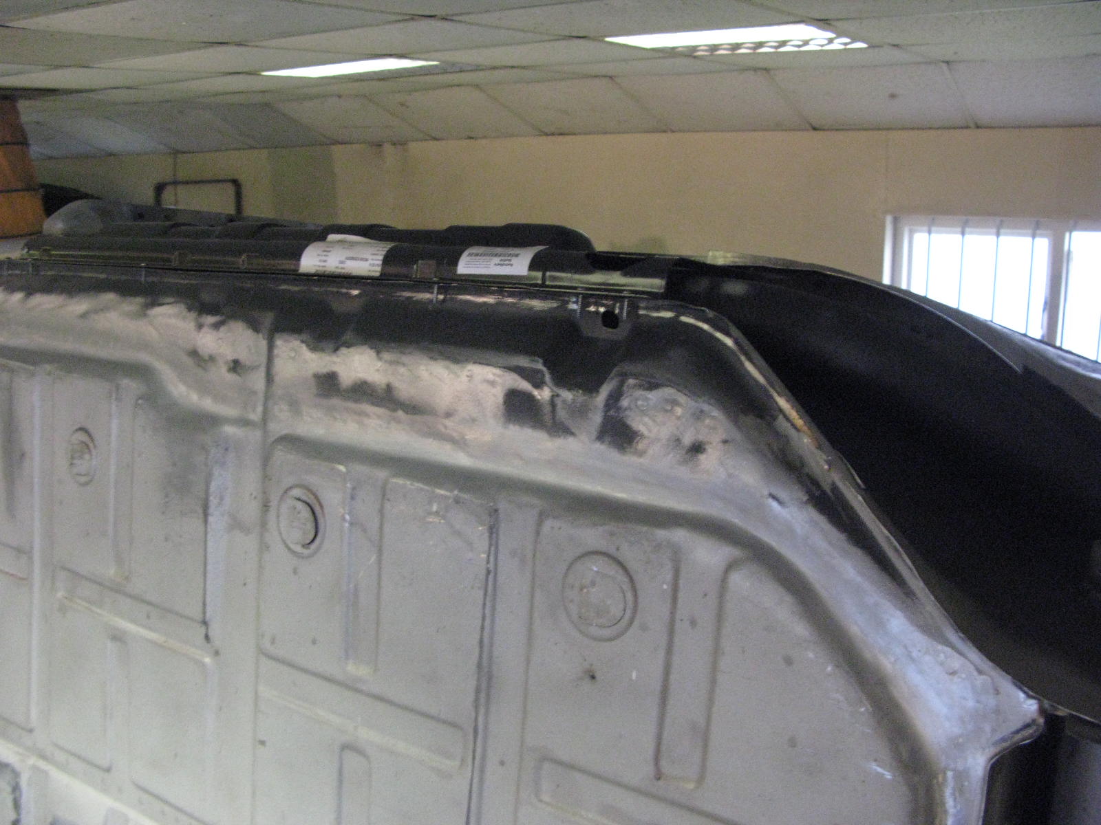
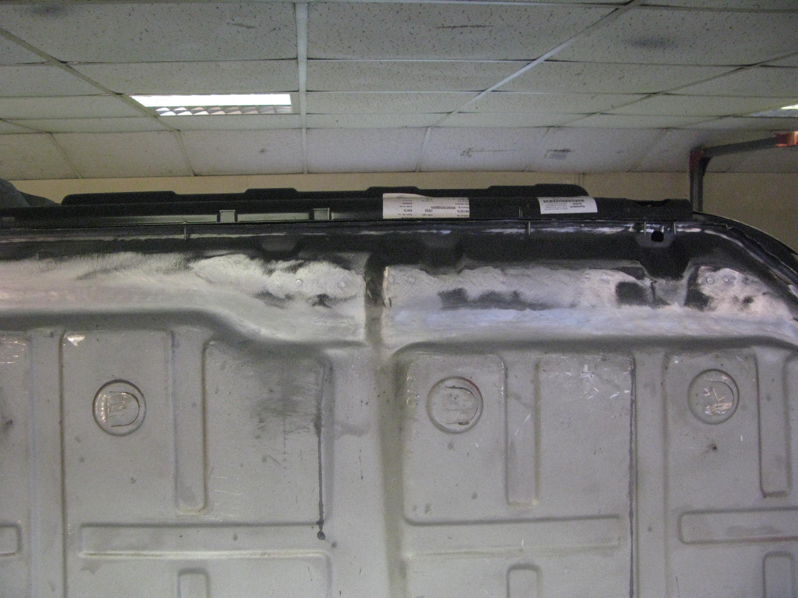
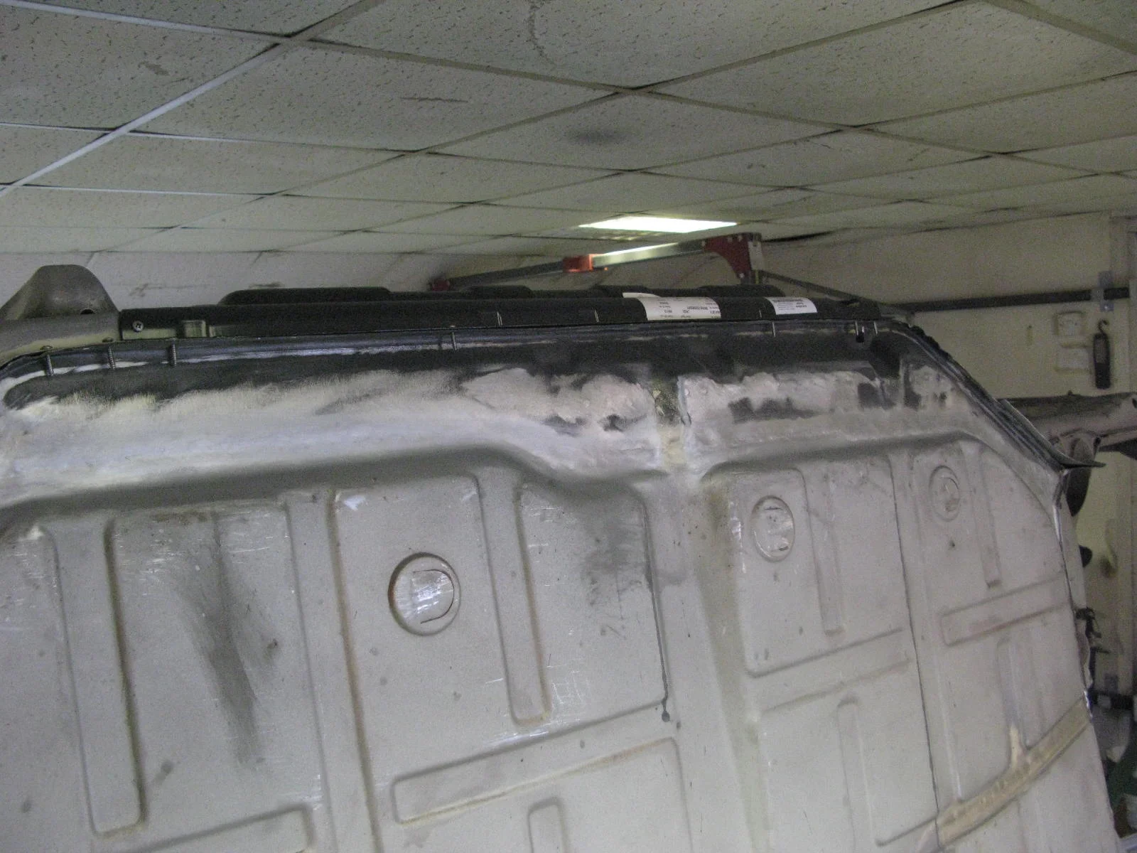
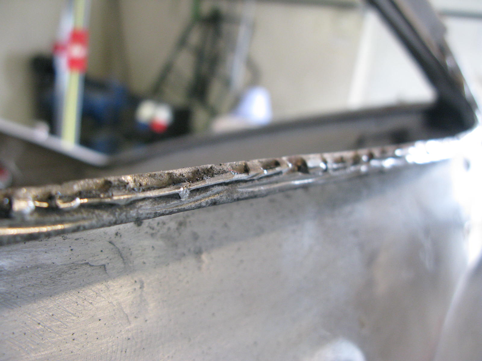
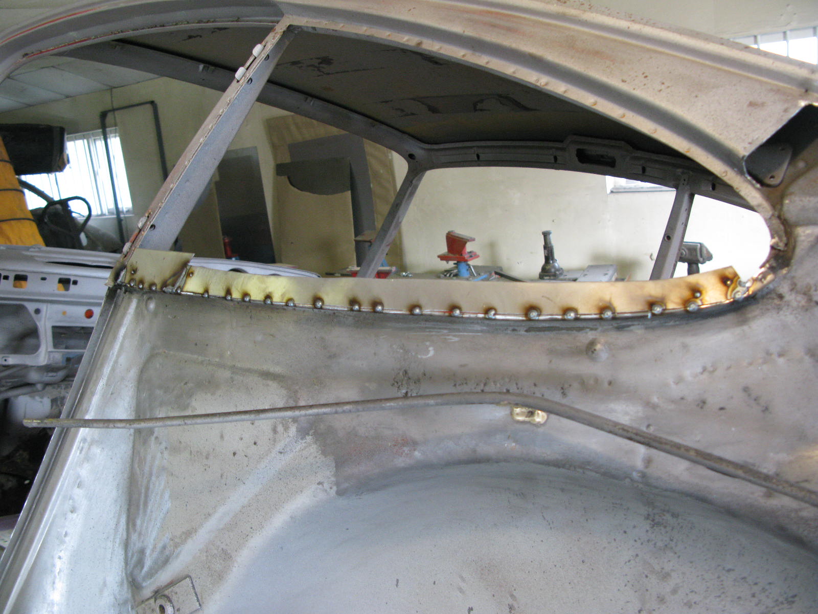
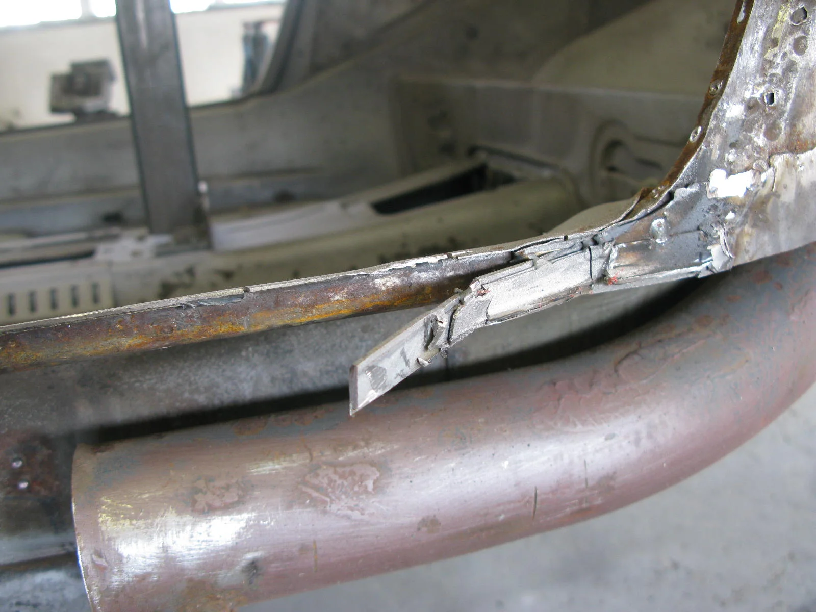
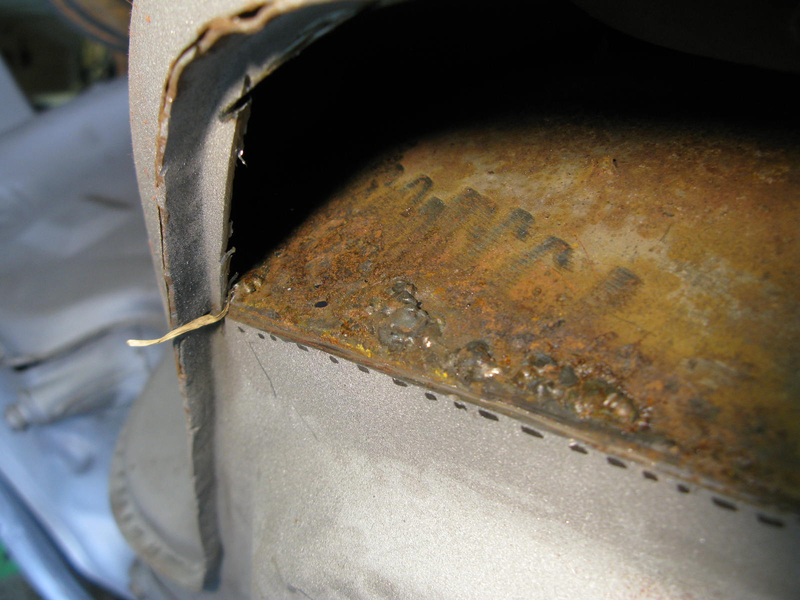
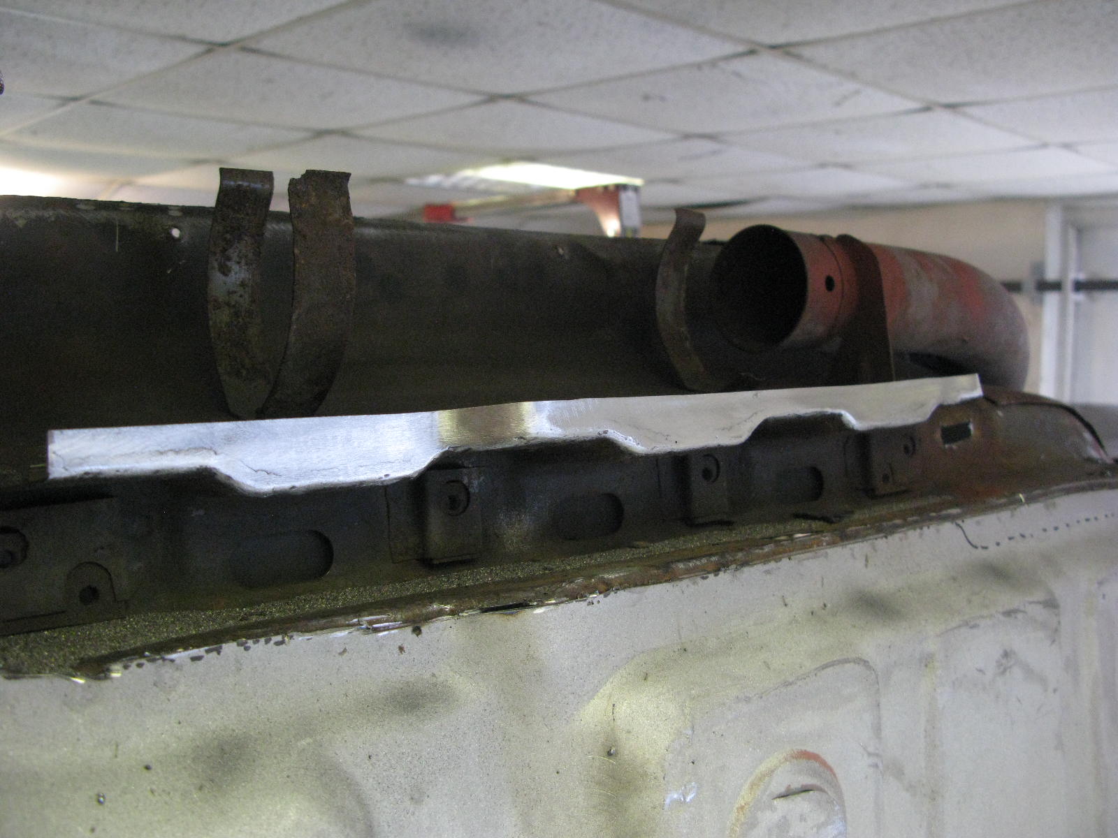
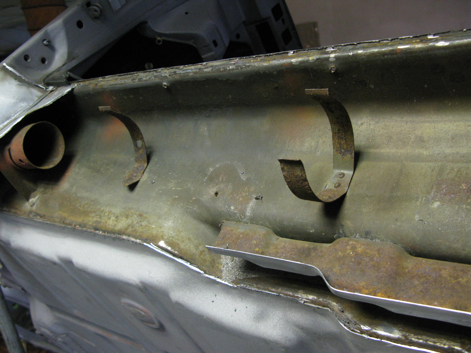
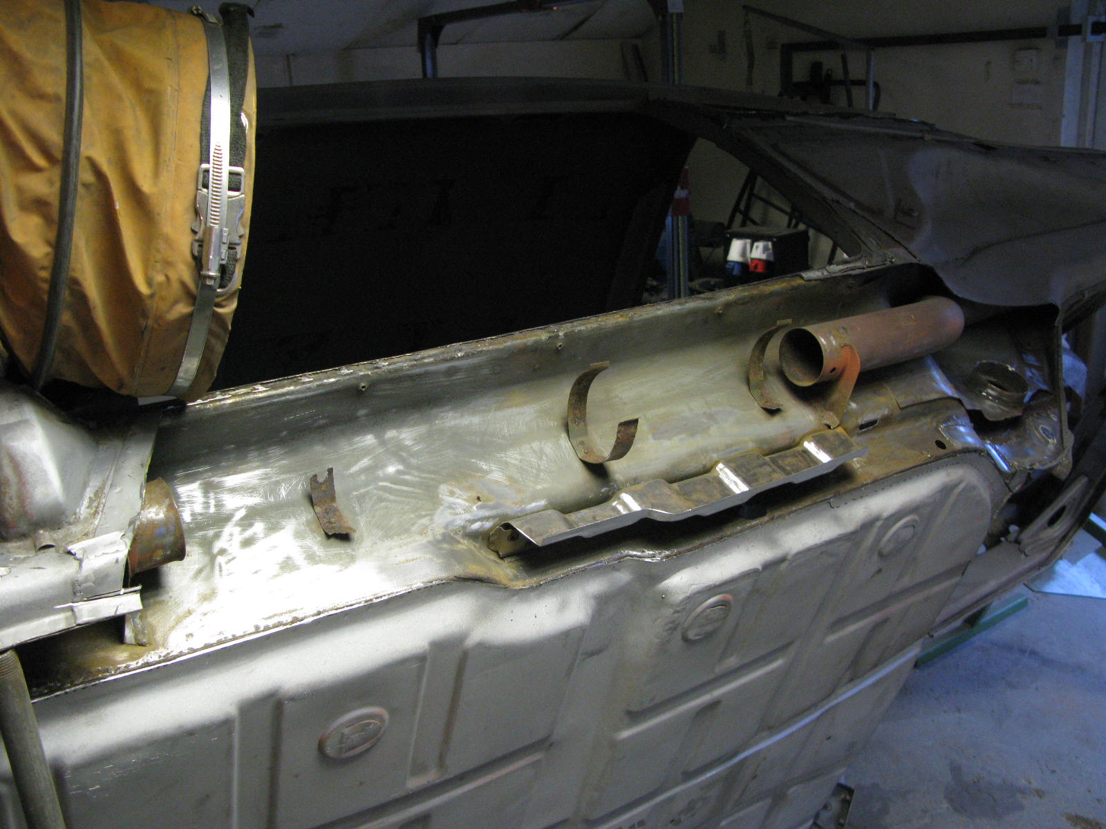
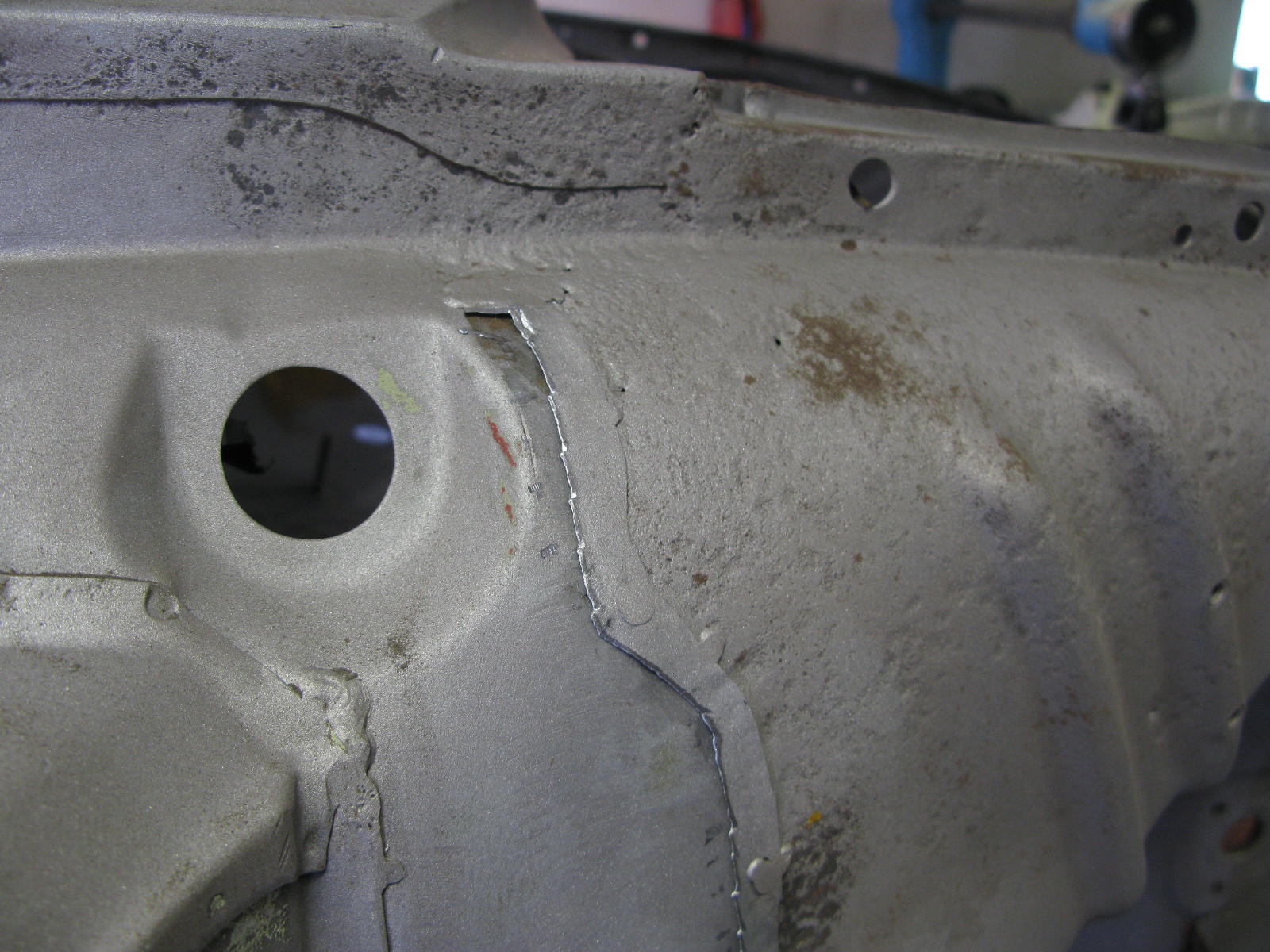
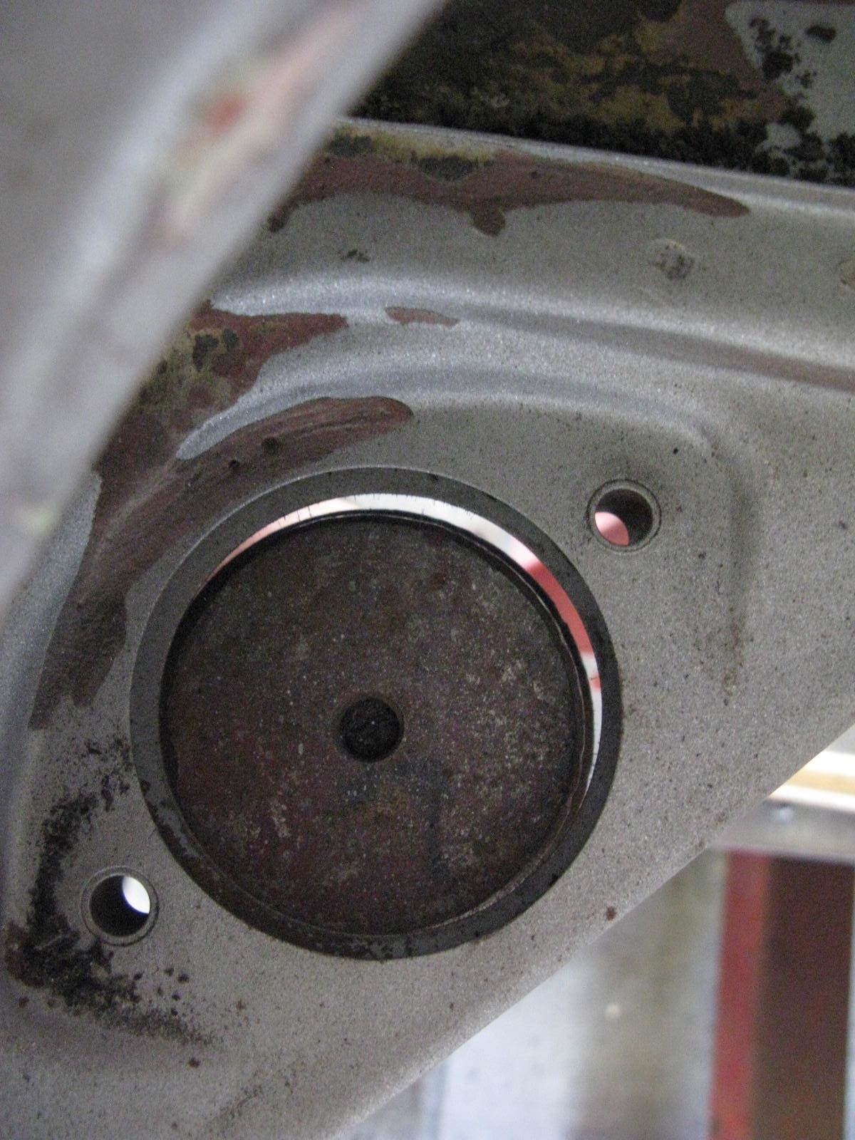
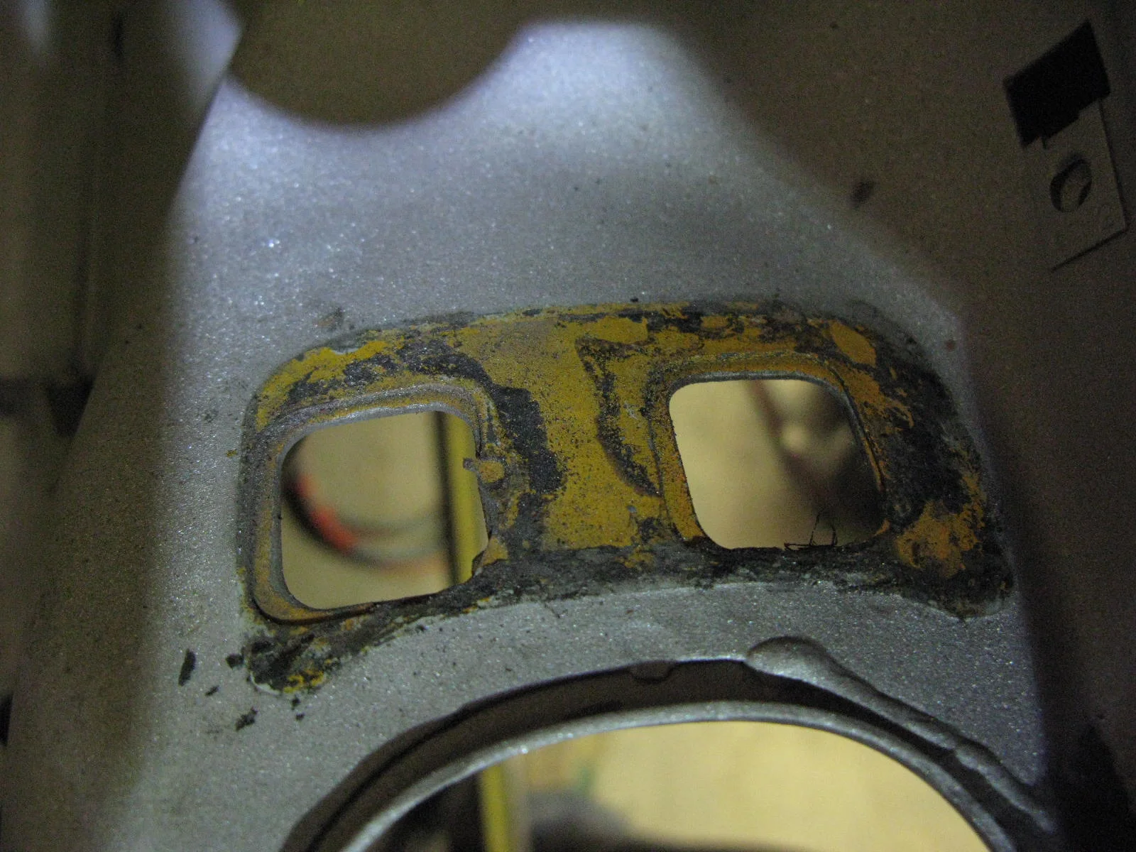
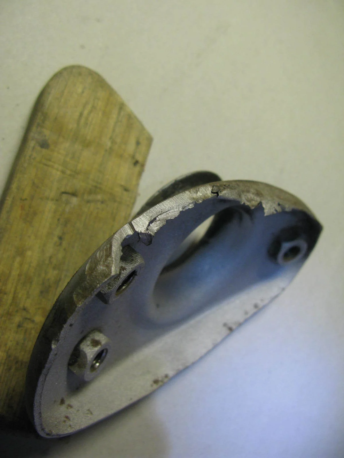
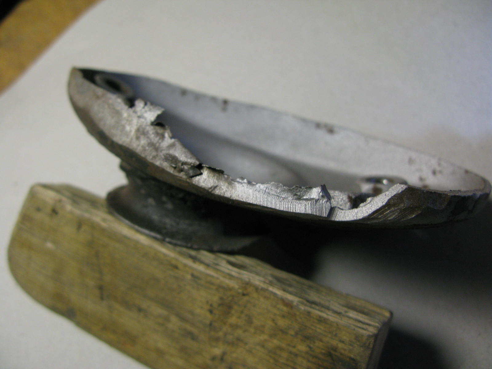
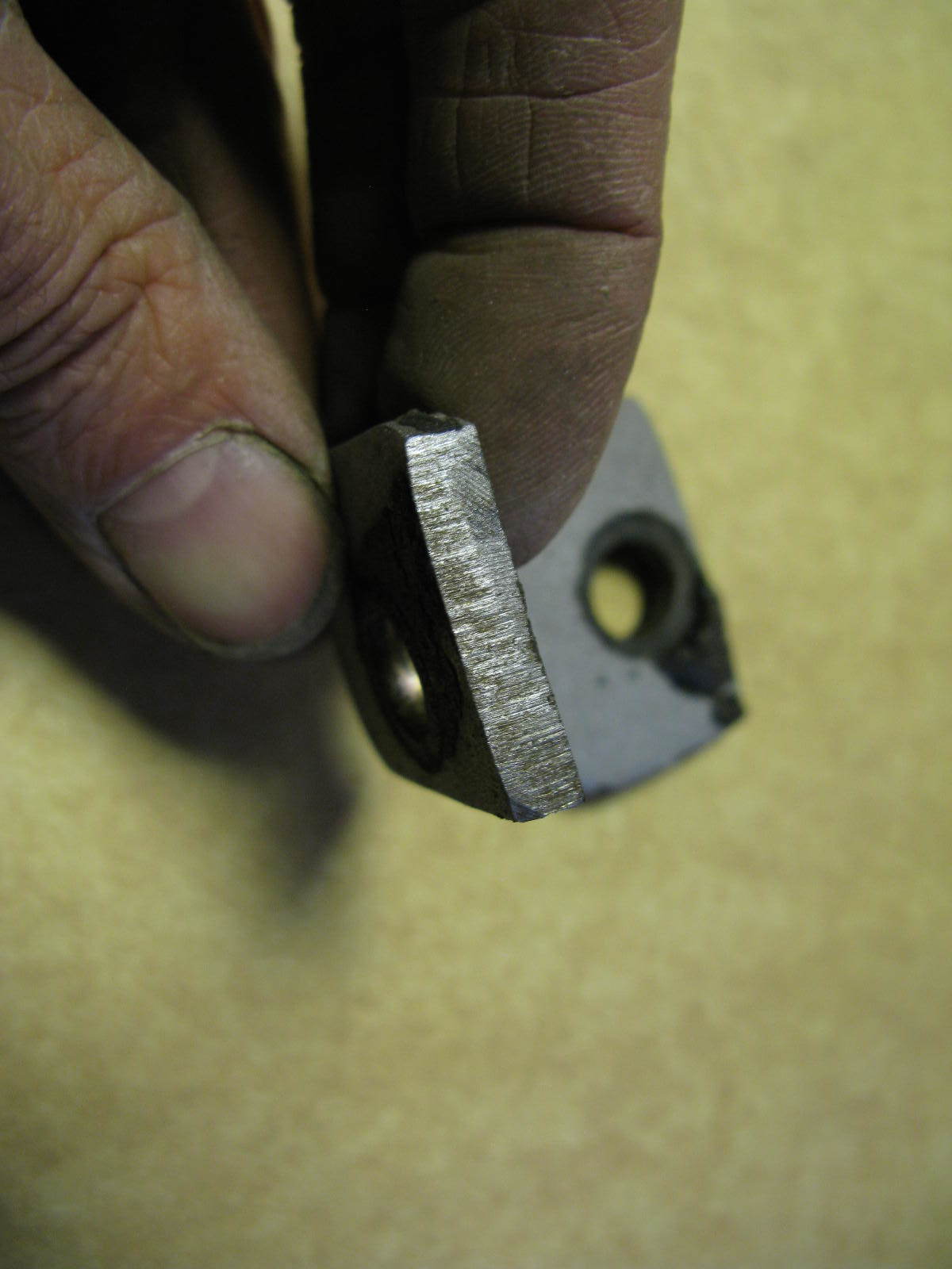
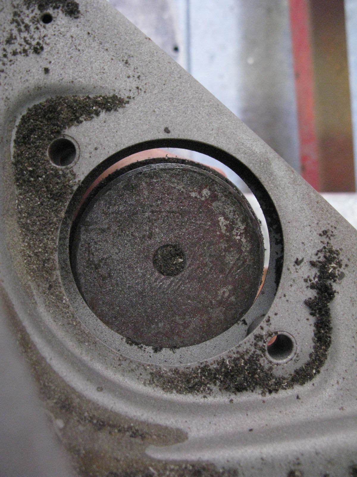
The front area of the rear inner wing had suffered through having had at least two B-posts welded to it, and then removed. 
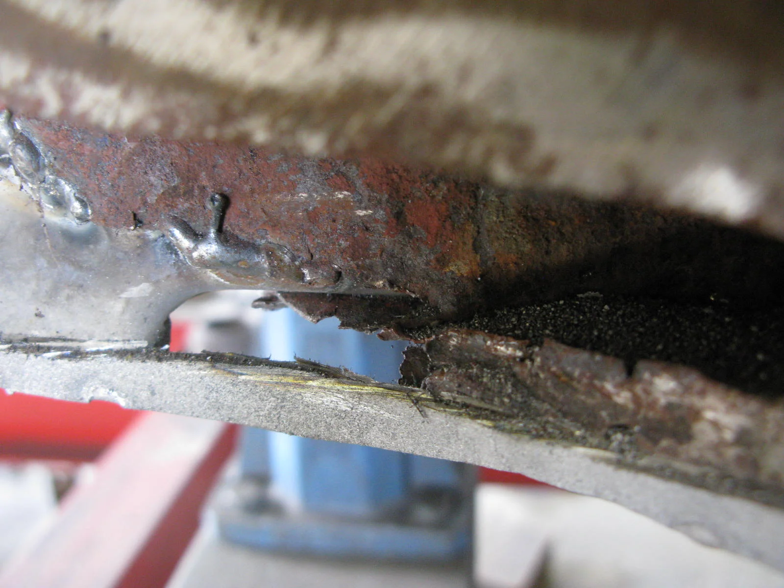
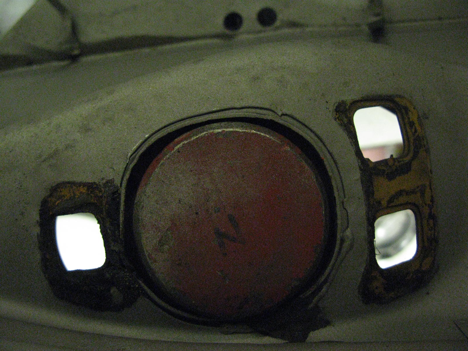
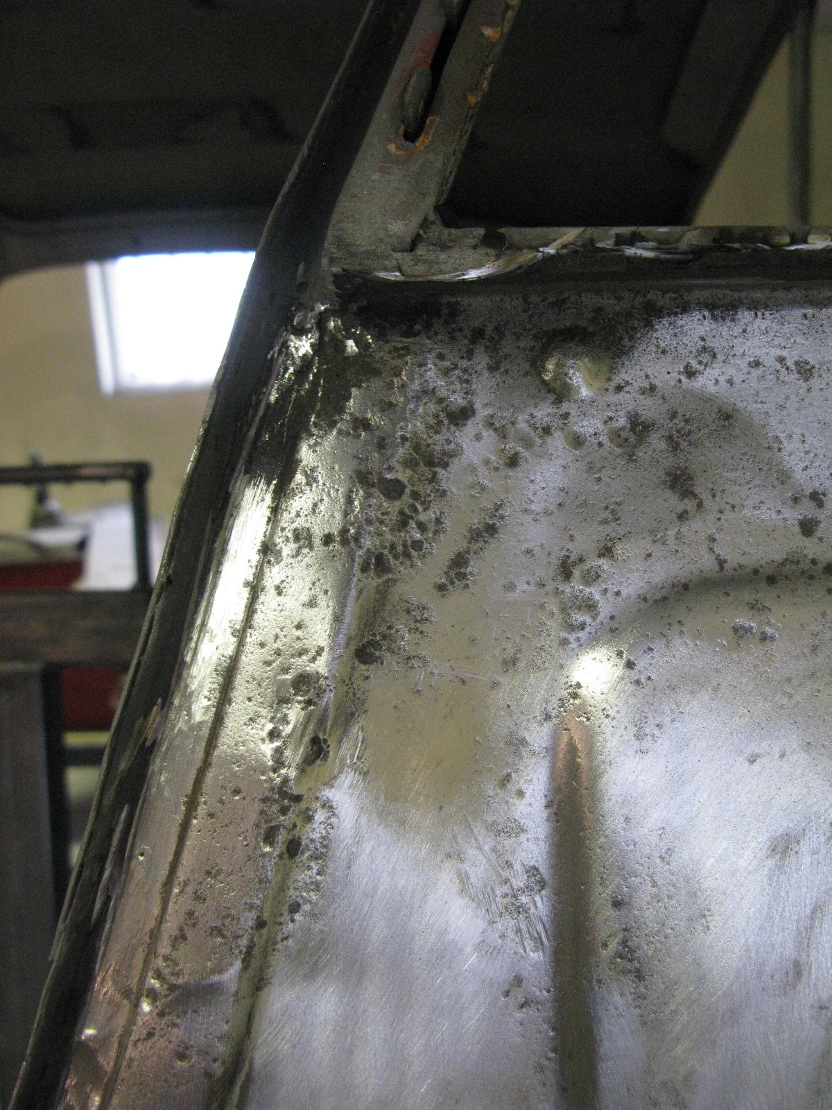
Additionally there were several areas of corrosion. 
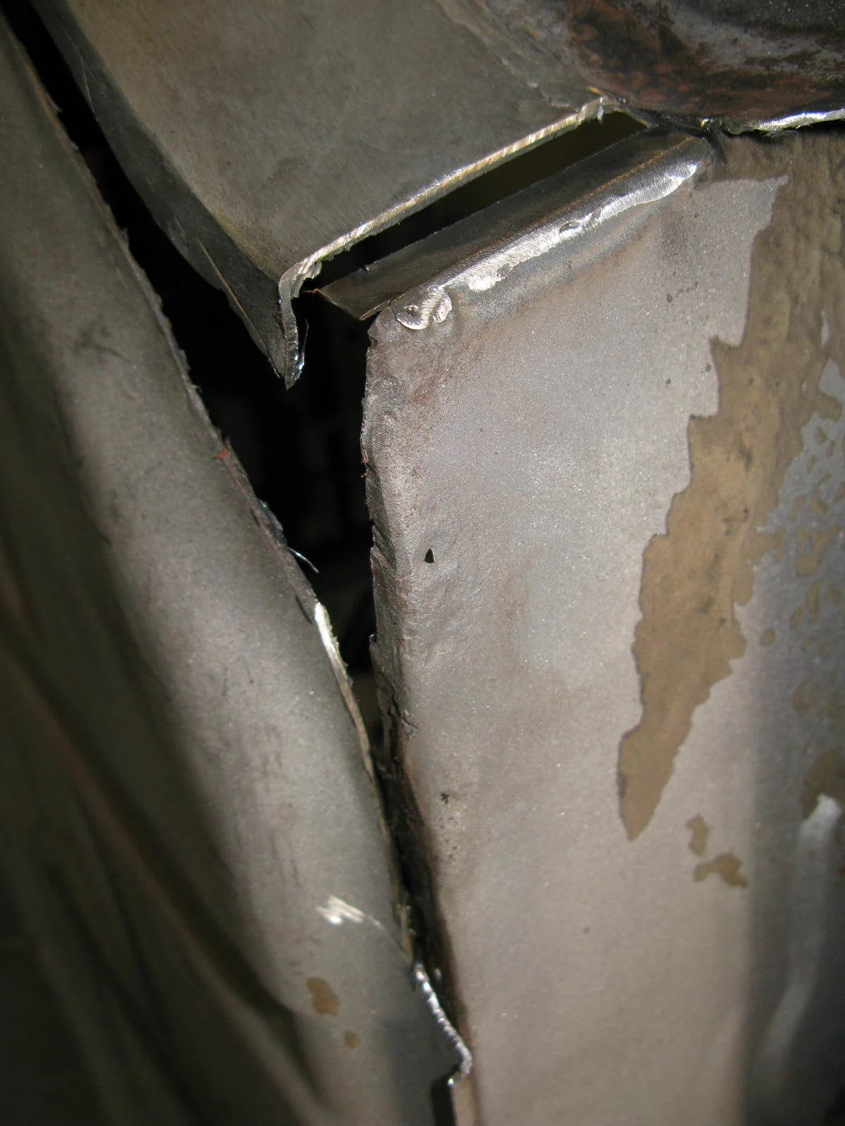
Replacement of this metal has the advantage that the welding on of the new B-post (rear wing) is much easier going from new to new metal.

Here's what we started with:

So it's another fairly complex repair panel, again allowing us to keep the bulk of the original metal.
Luckily Barry says:

One of my favourite repairs!
He's cheerful today.

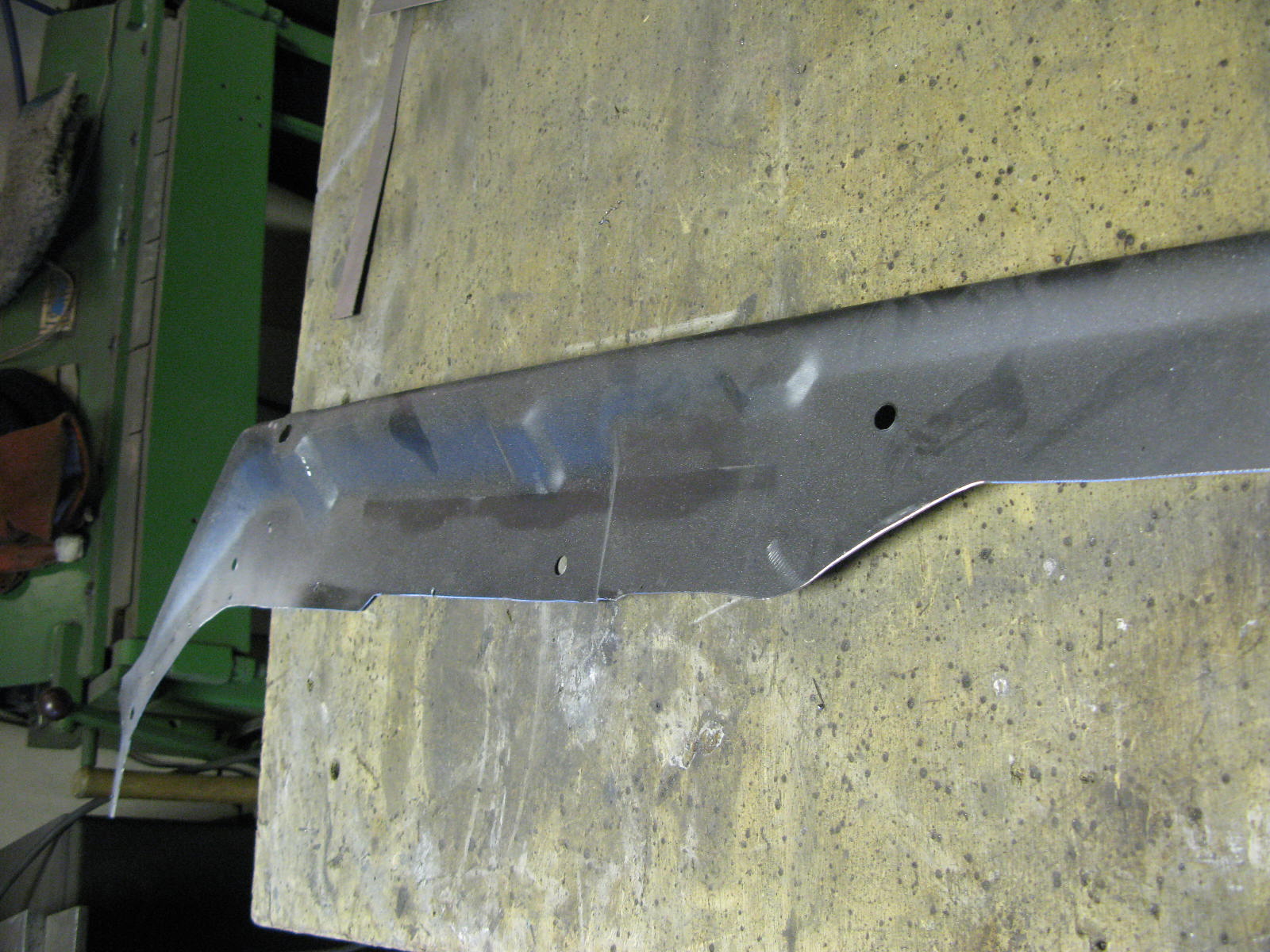
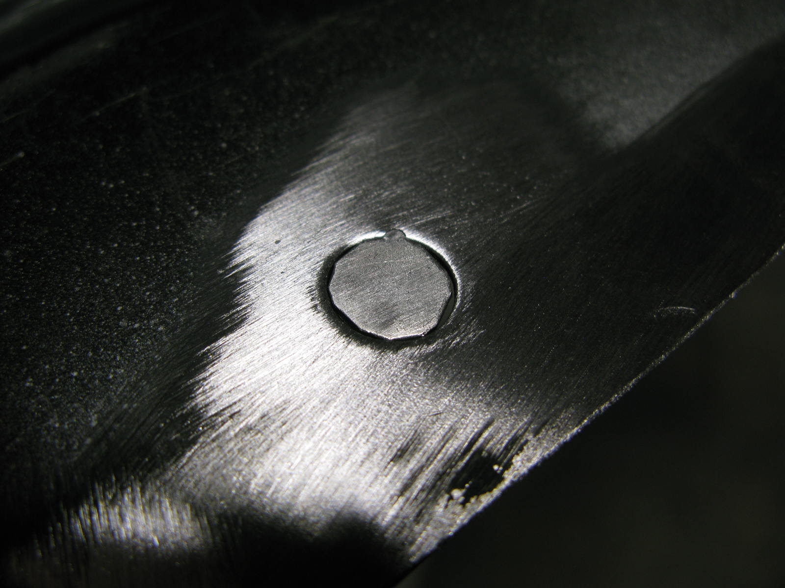
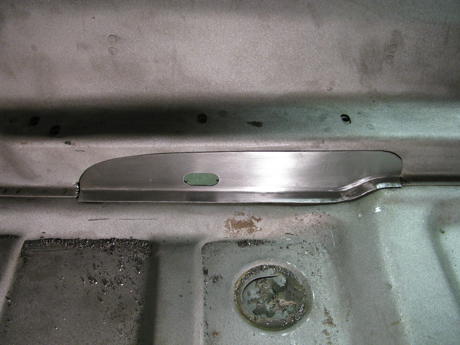
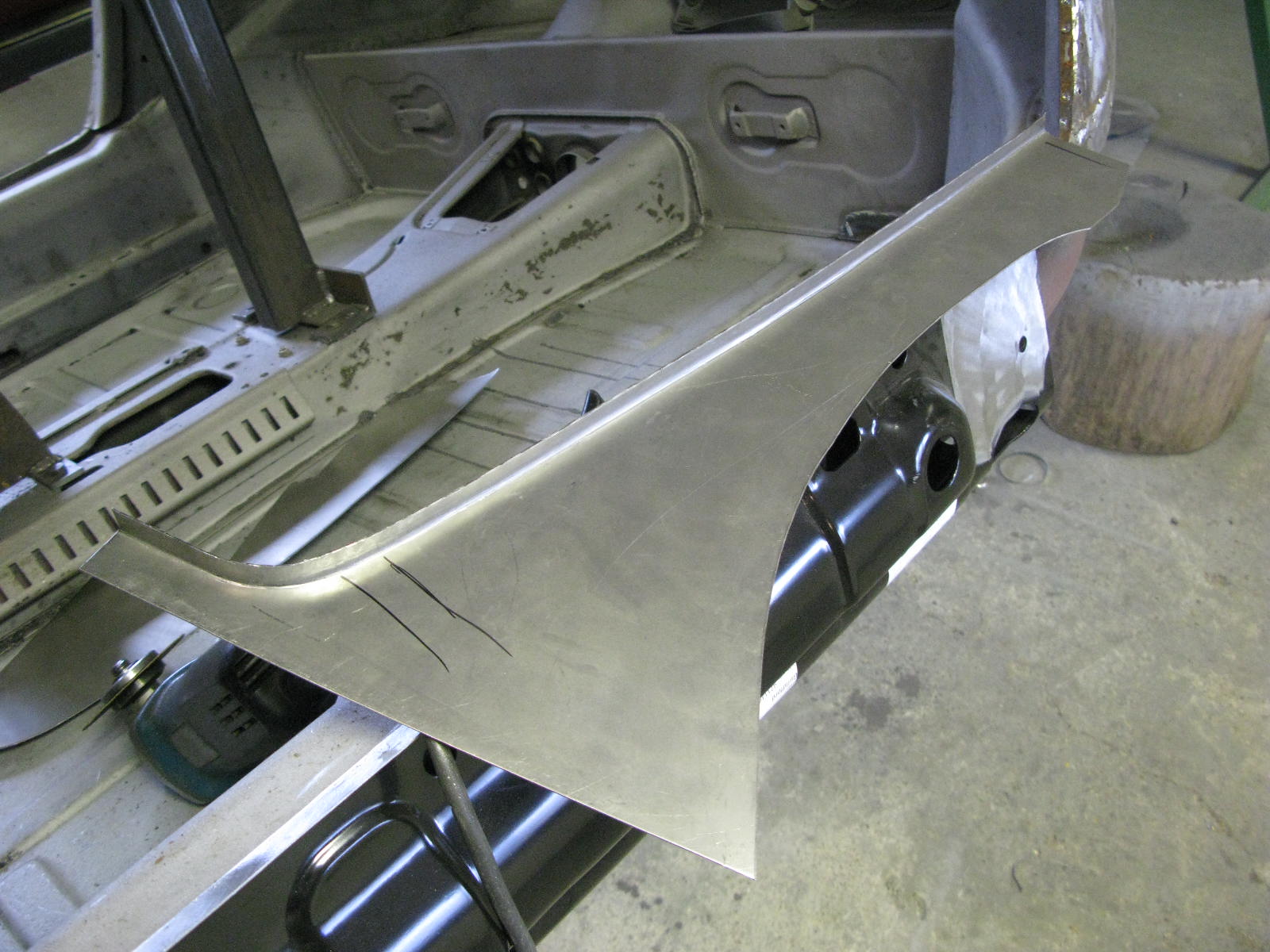
I've got some tooling I made up last year for the Pullmax machine, and it makes it very straightforward to produce the pressing in this panel.
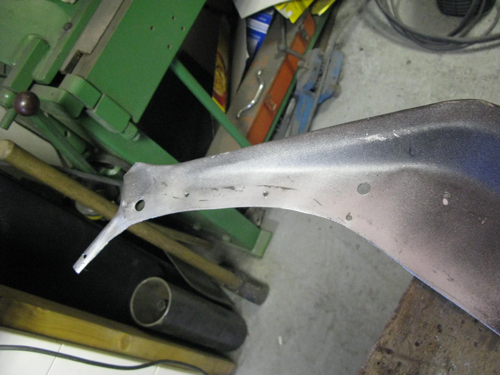
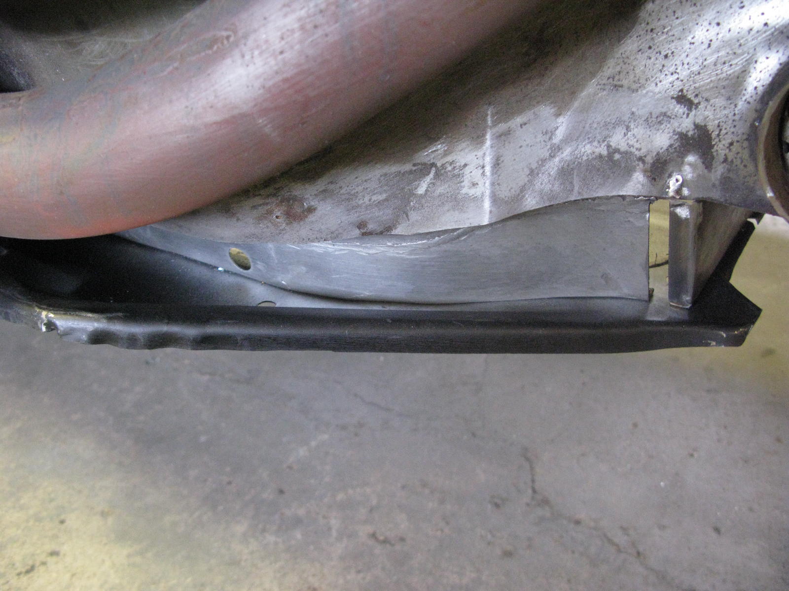
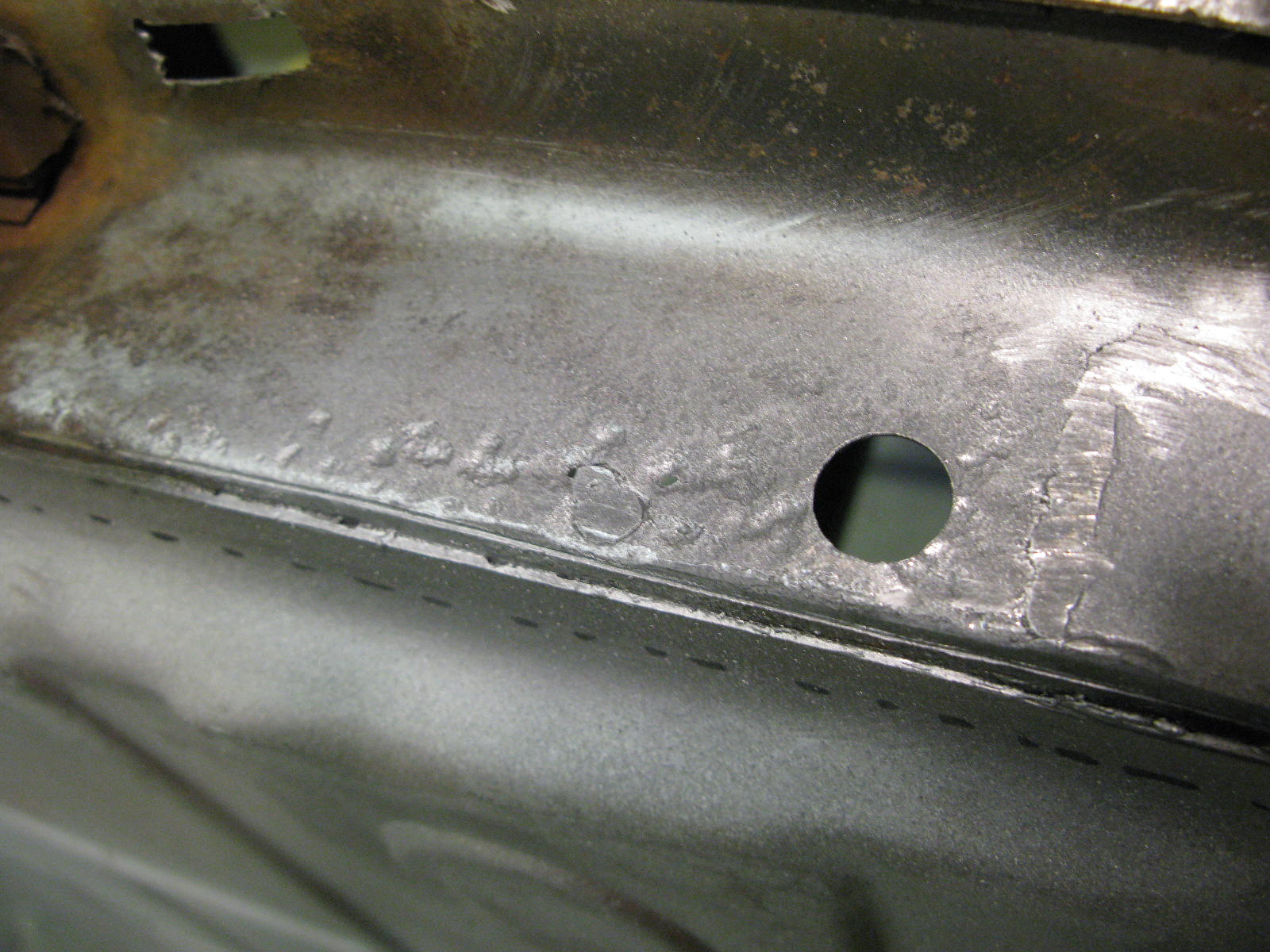
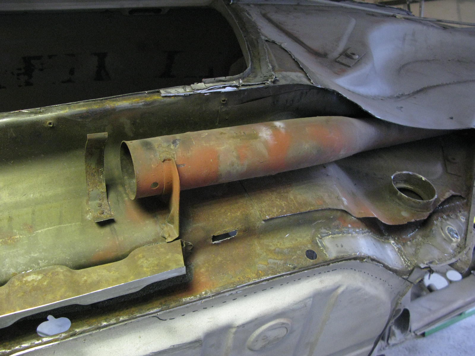
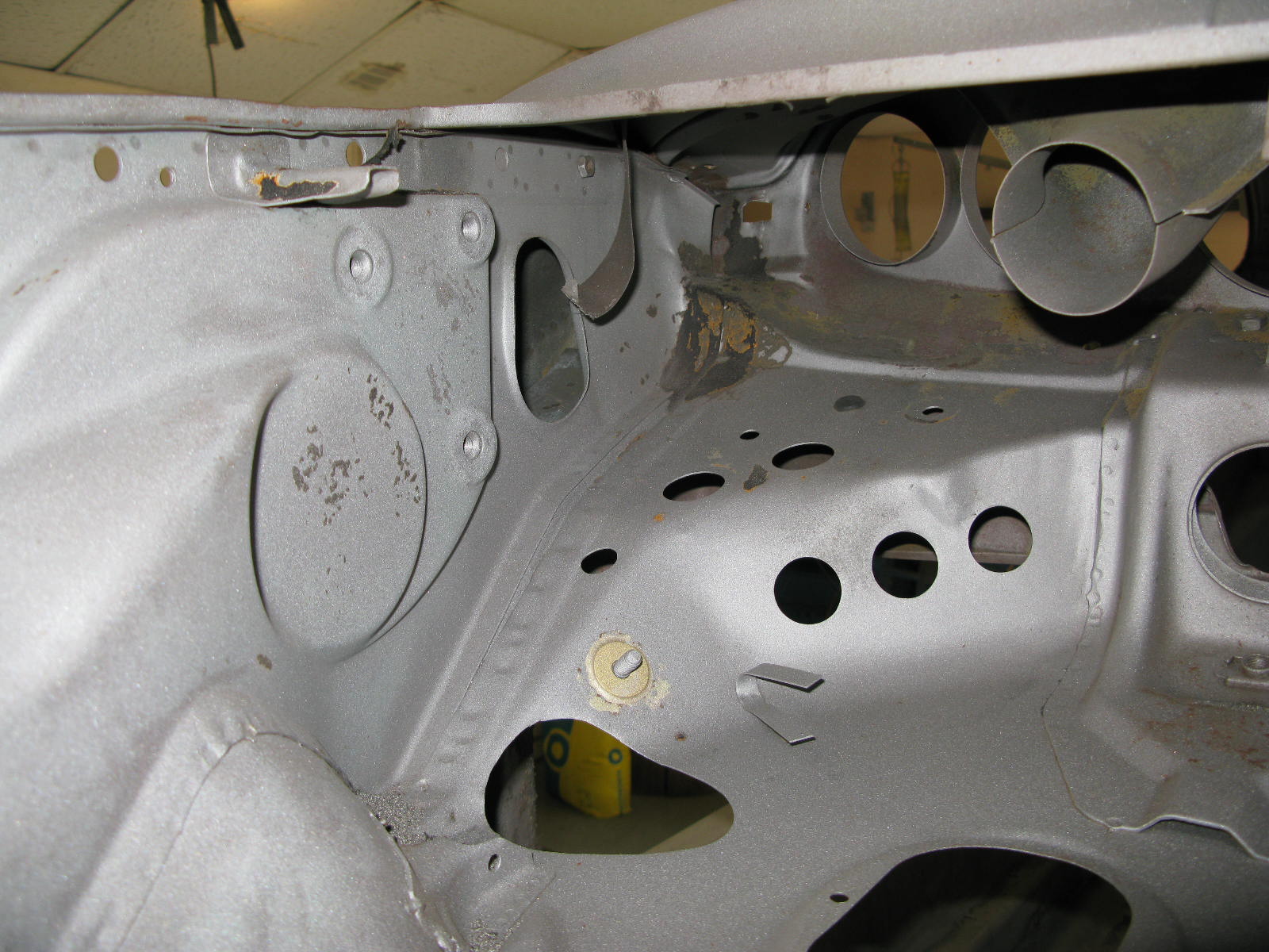
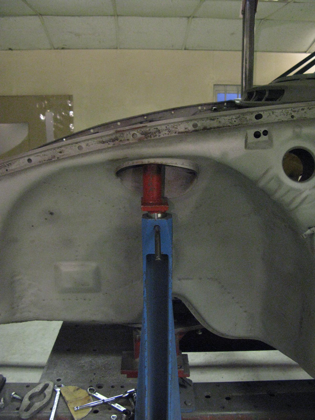
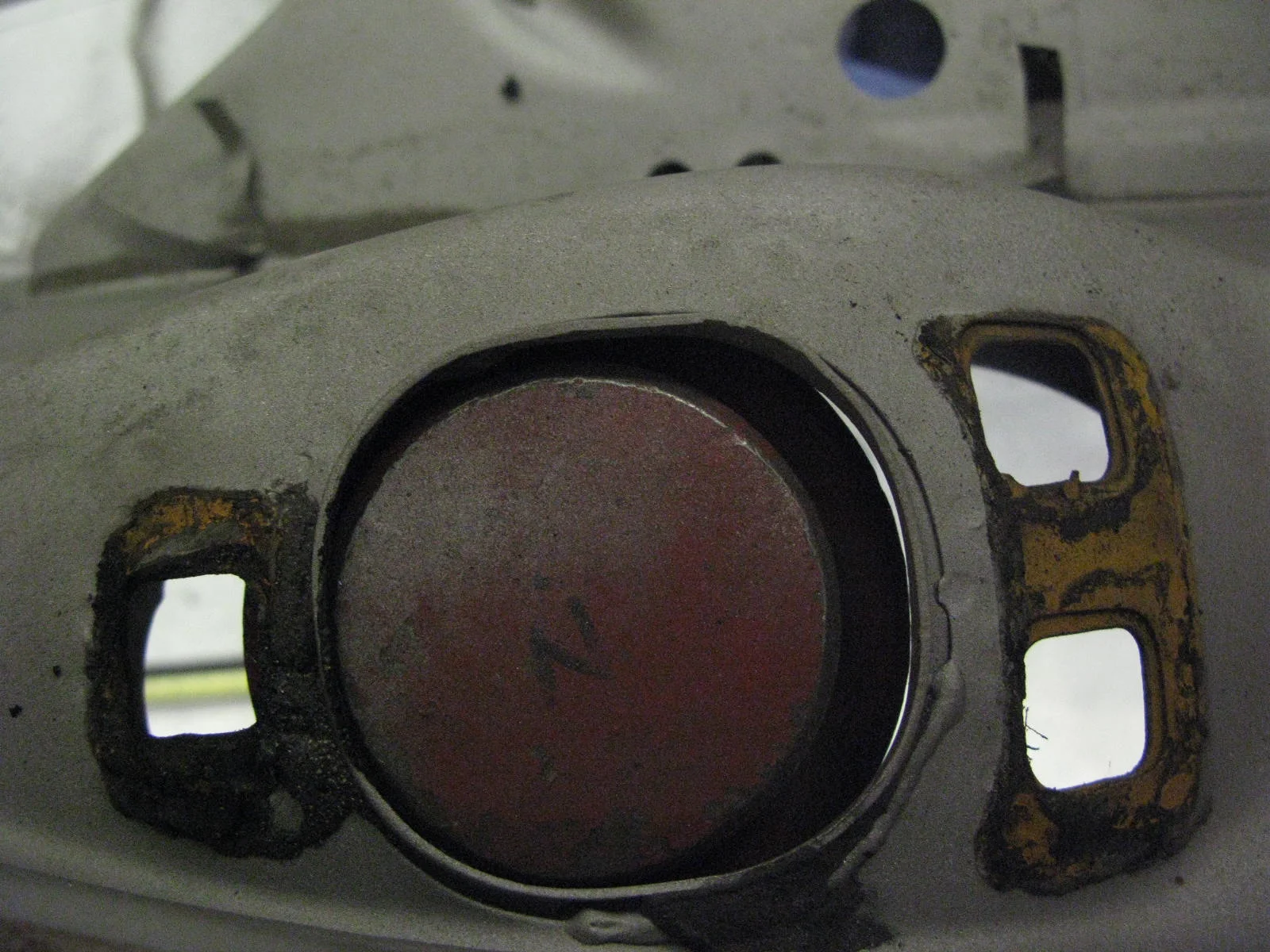
There is some tricky shaping to do around this area however, as the inner wing has more curves (in different directions) than might be assumed.
There is a degree of shrinking / stretching that needs to be done in order to allow the panel to lie nicely relaxed on the parent metal, ready for scribing in.

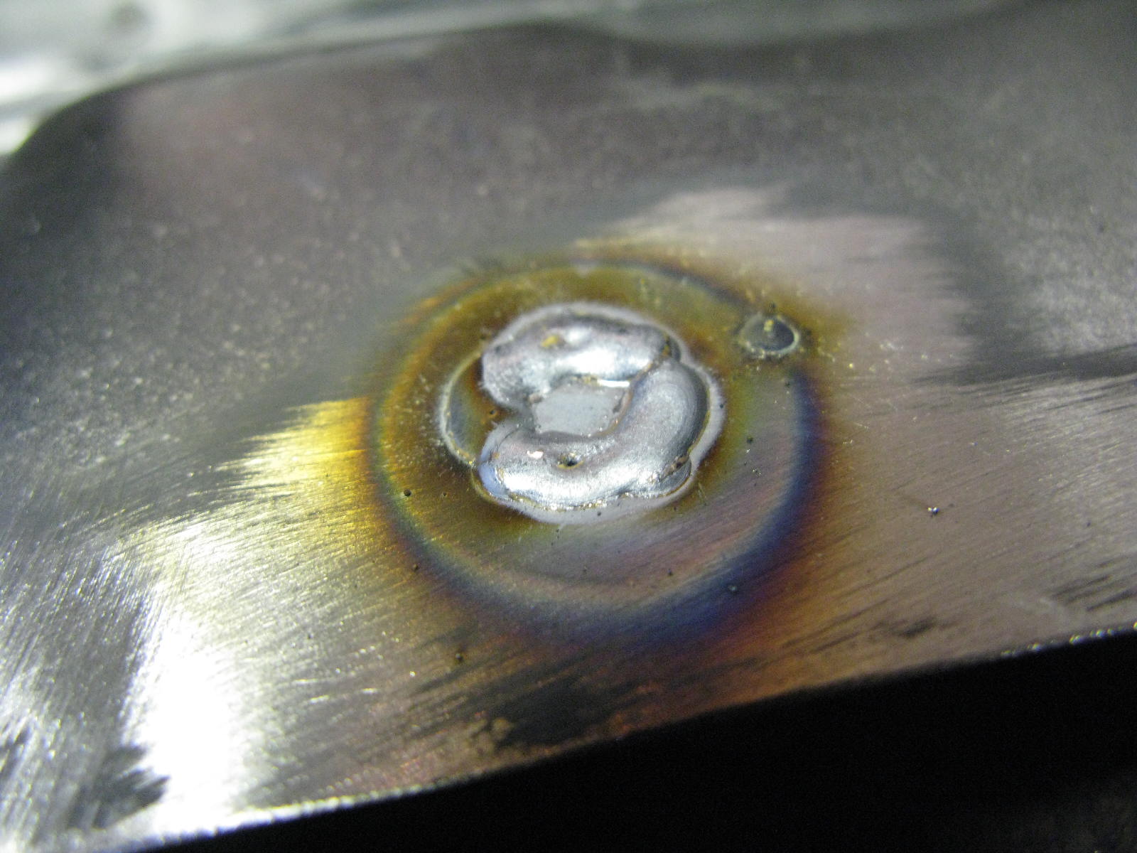
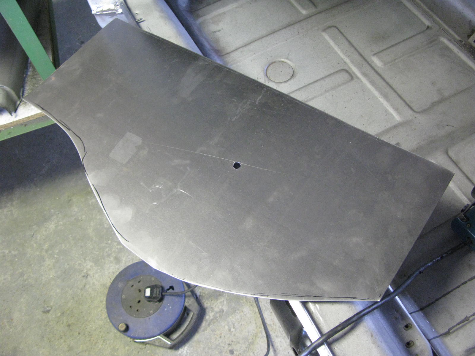
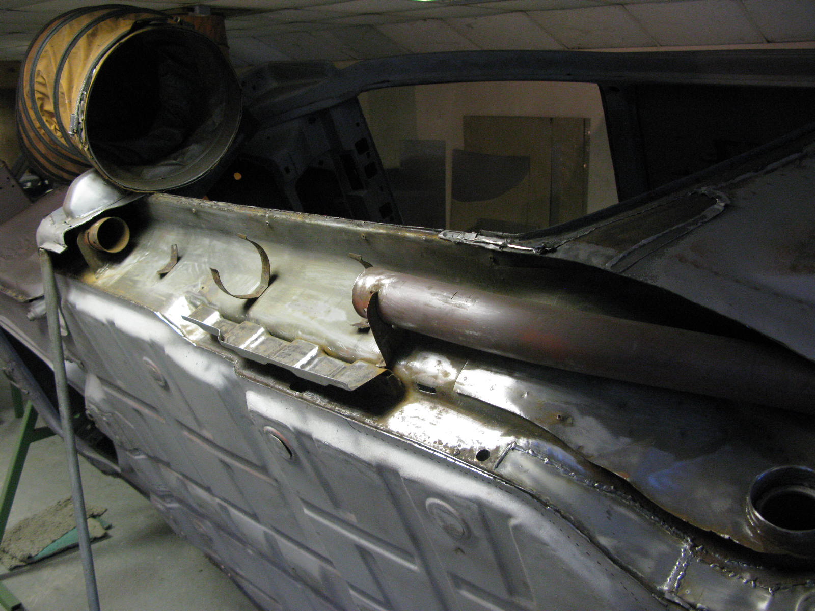
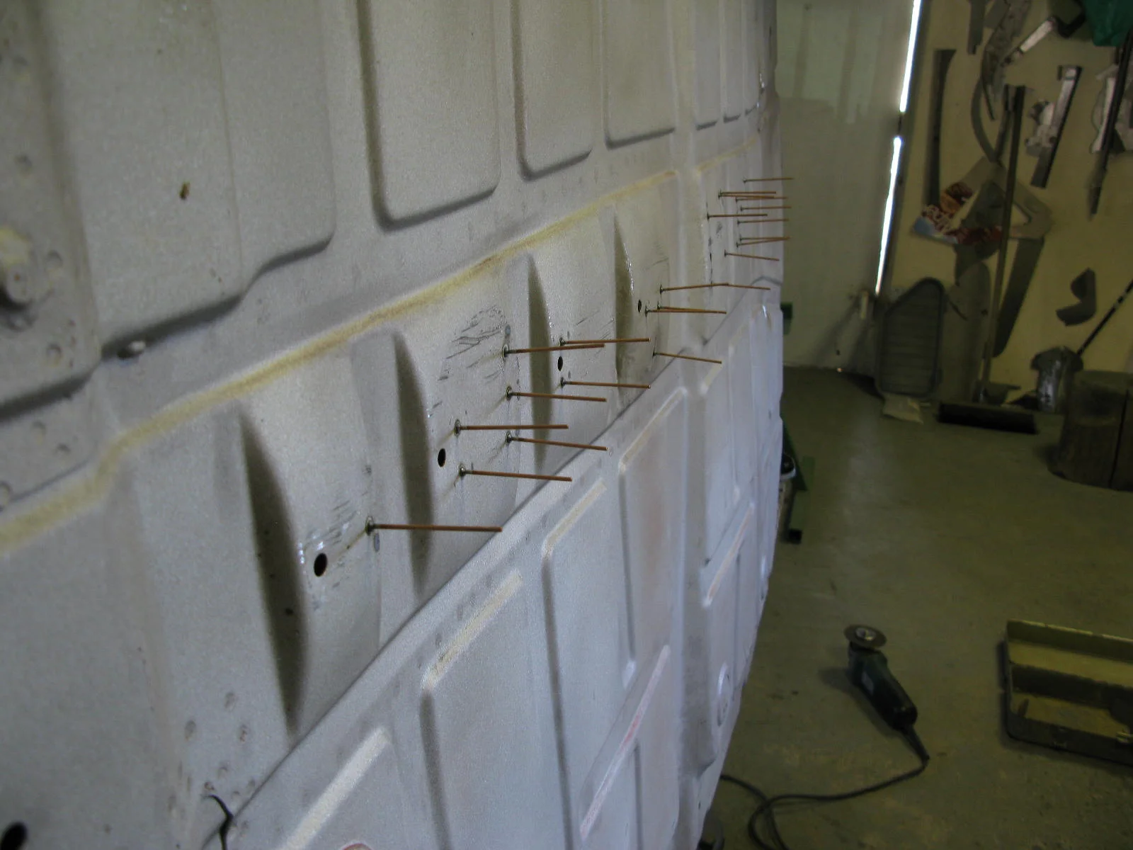
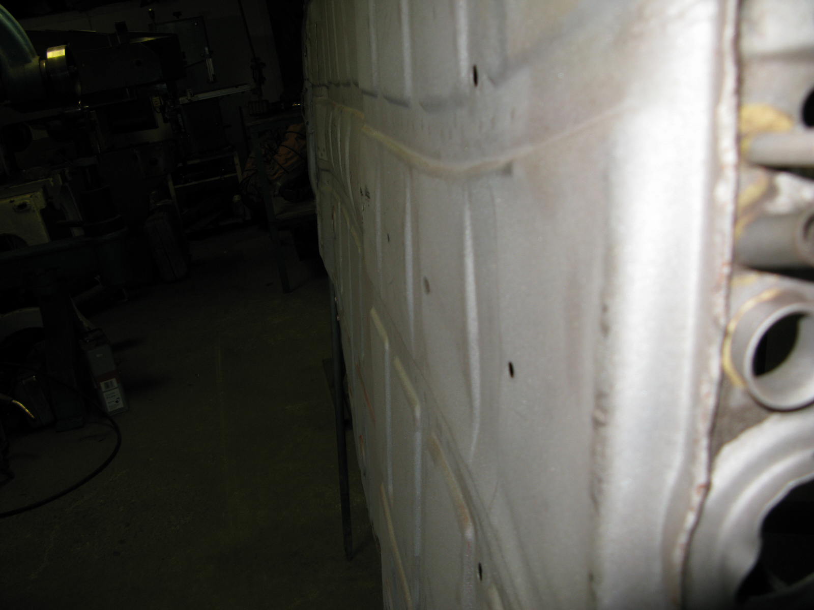
The repair panel fabrication process looks like this:

"Very straightforward", I'm sure we can all agree...

All that remains is to chop out the old bit and bung in the new bit. By now I had mastered the required technical language.

2016 MetalworkRichard Fry
LH Floor Edge

Finishing off the floor edge repair panel, and welding it in. The original floor was mostly very good, so these edges are the only new bits.

With the inner sill cavity all cleaned up and primed, the new floor edge (previously scribed and trimmed) could be prepared whilst the sill area paint was drying.

There are all sorts of holes in the floor edge, only two of which we want, and even those are 10mm rather than our 8mm.
They all get welded up, and then I'll drill some new 8mm's later on. Each hole gets a little custom disk, this gets dropped in and hammer and dollied until it sits in the hole unassisted. The area is welded up, ground back and linished smooth.
This is repeated for each hole.

With the inner sill area dry, the various weld sites are stripped of any etch primer over-spray, and re-primed with Wurth weld-thru zinc-rich primer. At last the floor could be welded in.

2016 MetalworkRichard Fry
Rear Window Flange LH

Both rear window flanges were a mess, presumably because of the previous rear wing replacements in the narrow->wide->narrow history of the car.
Here's the LH one being sorted out:

2016 MetalworkRichard Fry
Top Front of the LH Rear Inner Wing

Including pimple. As Barry explains:

Only point of interest is the little pimple. Made simply with a round chisel knocking the metal into a 13mm socket. So low tech.
There is one trick however, and that's to form the pimple first, and then overlay the cardboard template to get the repair's outline. This ensures the pimple is spot on, position-wise.

2016 MetalworkRichard Fry
LH A-Post Base

As previously mentioned, we decided to keep most of the A-Post bases, so...

The A-post base was just slit off, new flanges added on and after the above, was welded back into place after blasting internally and priming.

The previous repair had skirted around the A-post base, hence the odd 'blending out' at the front on the 'before' picture. Later on, anything that shows here will be run over with the big single sided welder for some cosmetic welds to be added. All the structural welding here has already been dealt with of course.

2016 MetalworkRichard Fry
LH Torque Tube Area: Centre Web Fabrication

Barry's words again:

This area is very tricky to make. Doesn't look much at all, but it's got to accurately fit in several places, one of the hardest being down to the floor, particularly as it curves over the rear of the floor pressing.

I've not got tooling for a 2.2 style inner web, but do have the left hand side for 2.4 and onward (RH pattern to follow soon). As a consequence I used my tooling to roughly fabricate a 2.4 style panel, and then free-hand re-worked it to an approximation of a 2.2.

These pictures show it in 2.4 style, a later sequence shows it properly in place. The 2.2 shell is helpful, in that the heater tube goes over the torque tube, giving many options on shapes to get from the upper area of the inner wed, down to the flange at the base. It gives lots of wiggle room compared to the 2.4, which have none at all.

As it is, it's got to follow the outer edge of the floor, the horizontal inner portion of the floor, the shape of the upper inner web, the torque tube and end up at the right place at the base ready to receive the new rear inner wing repair. There's a lot going on here! The sad thing is, to glance at it, you'd think it was an hour or so of rough bashing to make the thing. Sadder still, it's buried deep within the car, and in all likely hood will never be seen again.

Last two pictures (sort of) show how the panel lies over the rear of the floor and back down to the floor base.

When I used to make this whole area 'freehand' it was nearly two days work to get it all to fit, and that was usually in three pieces. BTW, all of my repairs are made from full 18SWG (1.2mm / nominal 48thou - actually 44thou) steel. It takes some shifting.

2016 MetalworkRichard Fry
LH Floor Edge Etc

Barry says:

As you can see, I have a little floor edge jig which I use if there's no original (trustworthy) metal to use as a guide for establishing the exact position of the floor edge. If this is out, it can tilt the whole outer sill, leaving you problems ahead when it comes to gapping between door and outer sill.

You can also see that the area beneath the torque tube is all stripped out ready to receive a new torque tube end and surrounding sheet metal.

And, just for fun, let's have a look at another old repair... 
held on with hope alone, no welds had penetrated through to the substrate at all.

2016 MetalworkRichard Fry
Base of LH Inner Member

In which we get to see some fabrication of small repair panels. Over to you, Barry:

With the recently replaced floor edge, together with the soon to be replaced A-post base area removed, work could start in tidying up the base of the main inner member (sill, chassis rail? You decide).

As you can see, the previous repairer had attempted to weld individual holes up. Sometimes this is fine if it's one or two isolated holes in otherwise good metal. In this case though, the whole area was replaced. Same principle was used all the way along. In the end, just one repair was retained right at the rear of the run. Not shown in detail, but that thin area near the round hole was replaced at the same time.

2016 MetalworkRichard Fry
LH Floor Edge Out

Barry says:

I measured the existing replacement floor edge, and it was projecting about 1/4in too far out at the front, and about the same distance inwards at the rear. Further down the line this would have caused a lot of problems with the outer sill to door gaps.

After a bit of a battle it was removed without going too far backwards on the good original metal. Note that the seat mounting reinforcement panel had only been welded on with three welds, rather than the 15-20 it should have had.

The whole area must have been 'as found' last time, as no attempt had been made to tidy it up, let alone paint it. I've set to with wire brushes, Scotchbrite and emery, and just about tidied it up. Once the area is welded up and ready for its new floor edge, I'll go in with the first hit of paint. Once the floor is dealt with, and just before the new middle sill goes in, it'll get another dose of etch.

2016 MetalworkRichard Fry
Centre Tunnel Dents

Moving on, here's the next instalment from Barry:

With the car mounted on the rotisserie, work proper could begin.

As is usual, the centre tunnel had been battered over the years, although I've seen very much worse. Much of the damage could be pulled out with welded studs and a slide hammer. Towards the rear, it was too badly crushed to retrieve using studs, so I removed the whole area, scraped and blasted it, before beating it back to the correct shape. With this done, the edges were primed in a zinc rich weld-thru primer, and the centre in black etch.

With the painting done, the area could be welded back in and the whole area tidied back up.

2016 MetalworkRichard Fry
Don't Have Nightmares

Bit of work on the underside now, so the shell moves to the Rotisserie. Before I post photos of Barry's witchcraft, let me share a "before" picture of the front subframe mounting point.
Someone presumably drove around with it like that.
Don't have nightmares...

2016 MetalworkRichard Fry
Front Inner Wings - Conclusion

Continuing the discussion of whether to keep or replace the inner wings, we also looked at the A-posts.

Barry says:
The A-posts (which get scrapped if inner wing replacement is undertaken) are both very good. In fact, I propose we even re-use the bases as we know they fit.
I'll chop them out, re-flange with new metal and weld back in once the inner wings have their new metal. We have nearly 400 euros to play with on these, and that assumes they fit perfectly. Yours, we know, do.

As you've doubtless guessed, we chose to keep the front inners and repair.
This makes me happy for reasons already covered. I'm glad to be keeping the original steel, especially bearing in mind the view of the scuttle / bulkhead and its join to the inner wings, as seen from inside the luggage compartment.

Given that inner wings are not exactly cheap from Porsche (best part of 3K GBP plus VAT for the pair), you might also imagine we're saving some money. Not so much, though. Individual repairs will take time, and the RD panels also cost. With that said, inner wing replacement is also many hours of labour (because they are so embedded in the structure at the top end), so the "pay for panels, save on labour" maths doesn't work quite the same as in other cases.

RD parts list was:
PP236TR ribbed area of offside front inner wing
PP204B tank support (non-battery tray)
PP236BL battery area repair
PP236BR ditto
PP280R torque tube housing area
PP280L ditto
PP221A parcelshelf
PP227B parcelshelf upstand.

2240.70 EUR for that lot, including VAT, shipping and modest discount.

And at my friendly local OPC:
Rear slam panel
Nearside engine bay seal holder
Heater tubes X 2

719.56 GBP inc VAT etc.
I did manage to get a cup of tea and eat some OPC biscuits this time, though.

2016 MetalworkRichard Fry
Front Inner Wings - Evaluation

With the pulling done, and the sills off, we now knew as much as we would ever know about the front inner wings. Time to make a decision - repair or replace?

Before getting into the details, Barry and I talked about pros and cons. Main problem with inner wing replacement is that they extend so far back toward the dash / bulkhead, and they obviously have a very visible join with the scuttle. So here's what I said to Barry:

My simplified thinking now is:

  • there are disadvantages to replacement, as you say
  • scuttle and its joins to inner wings are really good, and those original inners / welds are meaningful for originality
  • front end twist is probably correctable, and we already knew we were replacing the entire front pan

... so it all comes down to how bad the inner wing damage is, hence how strong and neat the repaired damage is going to be.

If the existing front inners are so significantly weakened by damage, or will be so visibly sub-standard when repaired that neither of us will be happy, it has to be new inners. Otherwise I’m back to my usual preference for keeping as much original metal as possible.

So Barry took plenty of photos and we had a discussion about what to do. Here's part 1 of what he sent me:

I'm leaning towards repairing both front inner wings. The internal structure on both is perfect, both from luggage bay and inside the cockpit area.

We can get all the repair areas we need from Restoration Design. I'm thinking that both of them have so much % of good metal, I'm sure we'd end up regretting getting up under the dash where the replacement of inner wing is so hard to conceal.

(If the scuttle had gone, or the inner structure of the inner wings had gone (they often do), or if it looked impossible to get the correct alignment, I'd say replace. )

The accompanying photos looked like this:

2016 MetalworkRichard Fry
RH Sill Etc

As per nearside, the offside wasn't over-welded and the inside of the sill area was just left as-is. No cleaning, no primer. Heater tube again poor. One layer of metal missing again, albeit a bit less area than before.

On a 70 car, this side has the through-sill oil pipes. Better news here - they are perfect. I took them away for a repaint.

2016 MetalworkRichard Fry
LH Sill and Torsion Tube Area

We need to make a decision on the front inner wings - repair or replace? And the sills are coming off anyway. So now is a good time to get them off and have a look at the bottom of the A posts.

As mentioned, the sills had been recently done as part of the previous part-complete resto. The car has not been used since then. So they should be pretty good, right?

Er... no.

Over to Barry:
It turned out that the nearside inner sill was barely attached at the top, and it just peeled away.

I was amazed to see that inside the sill area, no attempt had been made to clean up inside the area at all, not even a dash of primer. The heater tubes on both sides have had it I'm afraid.

I was also surprised to see a whole layer of metal just cut away and left out altogether at the rear.

Not a pretty sight.

2016 MetalworkRichard Fry
Pulling: Before and After

Some photos before and after pulling.

Front strut top mounts before and after:

Engine mounts before and after:

Front screen jig before and after:

2016 MetalworkRichard Fry
Pulling: Strut Towers

With the car held down to the jig by means of the various brackets that now fit, plus a pair of sill clamps, the front towers could be pulled.
The Porta Power is lifting the offside tower a bit, whilst helping it in and rearwards a little.

At the front, the current front pan doesn't fit the jig brackets, but I was able to lock them in one hole down (these have an upper and lower position), and then use long bolts / screws to hold the front of the car where I wanted it. Later on I'll weld some temporary straps between front of inner wings and the jig-bed whilst the front pan comes out. There is still some spring in the area, but as more and more work is carried out, I'll work this spring out before any new metal goes in. In the meantime, those ugly long bolts are holding everything just-so.

Whilst on same subject, all that pulling around has got the nearside torque tube end into the correct position. The four bolt 'receivers' though are a different matter ...

2016 MetalworkRichard Fry
Pulling: LH Side and Rear

Barry says:
The whole of the nearside of the car needed to go forwards a fraction, so I did this with the Porta-Power. This corrected several problems all at once.

The next issue was that the rear was slightly bent over to the nearside. This was corrected by means of drilling, bending and welding on a 3mm steel strap for the dozer to grab. This worked well, and if the need arose, the plate could be cut off, the welds linished and the rear slam panel none the worse for wear.

It was then time for some more work on the back end, this time in a vertical direction. I'm omitting a bit of detail here - Barry is extraordinarily (in my view) open about his methods, but this bit has a couple of trade secrets.

Anyway the news was good:
As hoped, the nearside was lower than the offside, which explains why the front screen jig fitted as it did, pre-pulling.
The rear nearside being lower than the offside pulled the roof back, pulling the A-pillar back away from the jig.

2016 MetalworkRichard Fry
Pulling

As shown in the previous photos, the shell is somewhat bent. So the first work package is pulling - applying fairly large forces to the car to try to pull it back into shape. We have the Celette jig to tell us how it's going, and also some other tools (like the screen jigs).

One of the indications of the front end twist was the front suspension mounts. They had been hacked about pretty badly, presumably to get the front suspension to fit despite the mounting points being misaligned. So on the jig they went.

To quote Barry, findings were:
Both of the Macpherson strut top mountings are pretty battered, and the offside one has been ground down, plus one of its clamp plates cut down. Now actually, I don't think the inner wing itself was out so far as to justify this wanton bodgerism, so I wonder if the upright itself was bent, and to a degree, this is what is trying to be corrected here?
... seems like a plausible theory.

Since I'm not using the uprights (struts) that came with the car, I don't much care whether they are bent. In fact, better if that's the problem not shell twist.

This is what I mean by hacked about:

... and this is how the mounting points looked on the Celette.
Not great, but not as disastrous as I had feared:

Moving to the back end, here are the "before" pictures of the engine mount points, relative to their correct positions on the Celette:

2016 MetalworkRichard Fry
Status Summary: Front Screen Area

I think this can be summed up as "not great". That jig should fit waaay better than this.

2016 MetalworkRichard Fry